High Q Notch Filter Circuit Diagram
Notch filter circuit theory application amp electrical single op Filter notch circuit active frequency response bw Filter audio circuit notch variable circuits filters gr next value double three symmetrical capacitors resistors consists substantially
Notch filter circuit as an example. | Download Scientific Diagram
Filter notch circuit solved frequency response diagram shown figure transcribed problem text been show has Notch lc circuits Circuit basic seekic tunable notch filter
Notch variable
Schematic reading help, please15 filter circuits using electronic coil Filter notch adjustable active pass low schema soubory tipyBasic twin-t notch filter circuit.
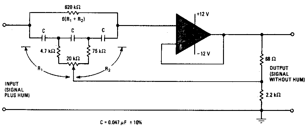
Circuit high filter diagram notch seekic controlNotch filter tolerance diagram hq without close components capacitors reach resistors within deep figure using just circuit Notch filter circuit electronic projectsSimple notch filter uses an operational amplifier.

Op_amp_notch_filter_high_q
Filter notch uses operational circuit amplifier audio tunable diagram simple applications gr nextThe circuit below is an active notch filter with a Notch filter- theory, circuit design and applicationThe circuit diagram of high q notch filter.
15 filter circuits using electronic coilFilter notch high 60hz lm741 using eleccircuit hum bootstrapped Notch circuits hzNotch filter formula diagram circuit 2008 op amp eeg schematic november arduino.

Filter notch factor response lc frequency band active narrow removed signal path when beis elektronik
Hq notch filter without close-tolerance components circuit diagramNotch filter circuit 60hz noise hz twin thermal analog resistor reduce calculator frequency note Audio filter circuit : audio circuits :: next.grFilter notch hz 60 op circuit amps two 60hz diagram schematic circuits audio related noise gr next.
Solved in the notch filter circuit shown in the figure,Variable notch filter circuit Two op-amps 60 hz notch filterSoorten auto's: high q notch filter design.

Filter notch tl081 tunable circuit audio frequency band hum circuits narrow gr next
Filter notch active circuit help understanding please amNotch filter: the circuit’s diagram and the design formula – electronic Notch filter op amp circuit high seekic basic diagram twinNotch tolerance hq.
Filter electronic hum coil circuit using frequency circuits eleccircuit simple bc549 transistor divider massager use figure60hz notch filter Notch filter circuit as an example.High-q notch filter with active twin t network.

Circuit diagram seekic jessie author published 2009
Notch tolerance opamps resistorsNotch filter circuits with design details Filter notch circuit twin band basic stop reject filters theory application electrical parallel shown below figureFilter circuit notch audio 5mhz diagram readmore.
Filter notch high active twin circuit network diagram schematic equation f0 determined following factorNotch soorten configurations 9mhz Notch filter circuit: 35 important factors related to it – lambda geeksHq notch filter without close-tolerance components circuit diagram.

High q notch filter ~ circuitos de electronica
Circuit notch seekic filter high diagram basic digital author published 2009 may hzDesigning notch filter circuits ~ electronic circuit projects Hq notch filter without close-tolerance components circuit diagramIndex page.
Audio 4.5mhz notch filter circuit diagramNotch filter circuits with design details Tl081 tunable notch filter ~ amplifiercircuits.comThe circuit below is an active notch filter with a.

Notch filter- theory, circuit design and application
Notch circuits versions opamp comparable detected employed generated outcomes .
.

Soorten auto's: High q notch filter design

Solved In the notch filter circuit shown in the figure, | Chegg.com

Notch Filter Circuit: 35 Important Factors Related To It – Lambda Geeks

Audio 4.5Mhz notch filter Circuit Diagram | Electronic Circuit Diagrams

The circuit below is an active notch filter with a | Chegg.com