Design A Circuit Of Full Adder Subtractor
Adder subtractor vlsi Draw the logic diagram of a full adder. create a 2-bit adder-subtractor Full adder circuit: theory, truth table & construction
Design a 4-bit adder/subtractor circuit with add/sub control line
Adder subtractor complement subtraction minus carryout overflow twos Adder subtractor converted inverter addition Design a 4-bit adder/subtractor circuit with add/sub control line
Adder bit subtractor parallel circuit bcd using adders circuits arithmetic ppt powerpoint presentation
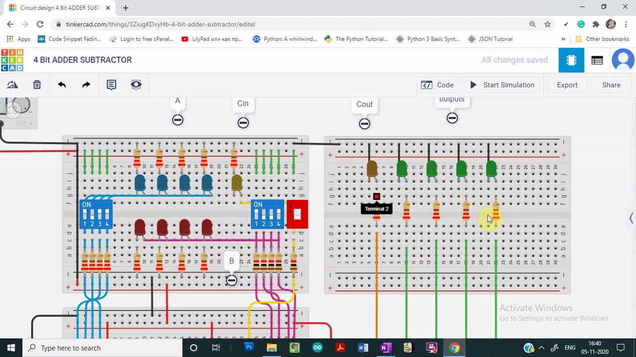
Adder bit circuit subtractor using subtraction sub borrow logic carry digital control input add additional signal note diagram low whenAdder subtractor tinkercad Adder gates subtractor implementation truth logic inverter converted xor circuits implement nor porte boolean logiche cpu logika diagrams penuh sederhanaAdder subtractor decoder circuitverse.
Logisim adder subtractor circuit evolutionAdder arithmetic carry subtractor circuits binary sum electronics digital output input number two Digital logicAdder half boolean implementation.
Virtual labs
How can a full-adder be converted to a full-subtractor with theTwos complement Adder bit subtractor circuit diagram block using logic drawBinary adder/subtractor.
Adder subtractor bit circuit carry ripple add control sub line overflow complement detection logic addition zero digital results questions findAll about technology: digital design : making a 32 bit adder/subtractor Adder subtractor binary logic combinational sub subtraction addersDemo: 4-bit adder subtractor using full adder ic with tinkercad.

Adder & subtractor ( half adder
Adder subtractor halfDigital electronics Logisim adder circuit bit subtractor technology fulladderComplement circuit bit multisim adder subtractor 2s.
How can a full-adder be converted to a full-subtractor with the4-bit 2’s complement format adder/subtractor circuit Full adder circuit diagramAdder xor rangkaian transistor ripple pengertian kombinasi.

Solved build the adder-subtractor circuit from page 18 from
Adder circuit construction binary circuits ibm sourav gupta qiskitAdder subtractor logic 4-bit serial adder/subtractor with parallel load – altynbek isabekovAdder subtractor circuitverse.
Subtractor virtual labs iitrSerial adder bit subtractor parallel module load schematics used Logisim-evolution 3: the adder/subtractor circuit.


CircuitVerse - Full Adder/Subtractor using Decoder

How can a full-adder be converted to a full-subtractor with the

4-bit 2’s complement format adder/subtractor circuit - Multisim Live

Adder & Subtractor ( Half Adder | Full Adder & Half Subtractor | Full

Full Adder Circuit: Theory, Truth Table & Construction

Adder - Classifications, Construction, How it Works and Applications

Draw the logic diagram of a full adder. Create a 2-bit adder-subtractor

Binary Adder/Subtractor | Electronics Tutorial